Foreword
UV mapping is a somewhat complex subject, as not only the placement of seams and unwrapping plays a role, but also other things like smoothing splits and texel density. We’ll assume that the model will be baked and used in a real-time engine; if it’s just for rendering, that’s fine too.
Here are some good videos and articles on the general subject of UV mapping
Become a BOSS at UV Unwrapping
26 Essential Blender Tips for UV Unwrapping Subdivision Surfaces
Software and Tools
UV mapping can be done in all kinds of software like Blender and Maya, or dedicated UV mapping software like Rizom UV, Headus UVLayout and Ultimate Unwrap 3D. More on dedicated UV mapping software in this video.
While most AAA studios like Capcom, Blizzard and Riot Games use Rizom UV, I’ll focus on Blender, as it has all the tools dedicated UV mapping software have when paired with add-ons. In addition to that, the choice in software won’t play that much of a role in the final output, but more so influence the workflow.
The essential add-ons for UV mapping in Blender are UV Pack Master, Texel Density Checker and UV Squares. Other add-ons worth looking into are Zen UV, UV Toolkit, Texel Tools and Dream UV. More on these tools at the bottom of this page.
Another helpful tool for UV mapping is UV checker maps or software built in distortion heat maps. They help identify stretching and distortions. UV checker maps also help visualize texel density differences between UV shells (islands), but more on that later. My favorite collection of UV checker maps can be found here.
Placing Seams & Smoothing Splits
Smoothing splits are a vital part of UV mapping. There are many different workflows, but mostly one places seams and creates smoothing splits at the same time. This is because a smoothing split always needs to be accompanied by a UV split, otherwise undesired sharp edges and artifacts will start appearing in the Normal and AO maps.
The ultimate rule of thumb
A smoothing split always needs a UV split, but a UV split doesn’t always need a smoothing split.
One can also use smoothing splits wherever UV splits are without increasing the vertex count, as the vertices are split regardless. More on that in this video:
One can freely use smoothing splits wherever UV splits occur without increasing the vertex count, as the vertices are split regardless. Smoothing splits also won’t cause any shading artifacts when accompanied by a UV split; so, one can simply add smoothing splits wherever UV splits are. With proper software or add-ons / scripts, this process can be fully automated. (Do check the result, however, because there are some rare situations where this won’t work; for example, it can have problems with complex partial mirroring). Here a video covering this:
Lastly, one should try to make UV shells as big as possible, to free up UV space, as every shell needs its own padding. For very long shells, it still makes sense to split them into smaller shells, for better packing results. Two other advantages of bigger shells are that there are fewer shells in total, so fewer potentially visible seams, and the vertex count in the game engine is reduced.
Helpful knowledge for placing seams and sharp edges in Blender:
| Feature | Notes | Hotkey / Location |
|---|---|---|
| Mark Seams and Sharp Edges | This unlike the right click menu works in vertex, edge and face mode. | Ctrl + E |
| Mark Seams and Sharp Edges via Edge Tag | In Edge select mode Ctrl select edges and in the pop-up menu add the desired tagging type | |
| Select Edges Marked Sharp or with a Seam | Shift + G or Select > Select Similar | |
| Select Sharp Edges | Use to place seams and sharp edges at edges that surpass an angle threshold. | Select > Select Sharp Edges |
| Smart UV Unwrap | Smart UV unwrap can often do the job for hard surface objects. | U or |
| Place Seams Based on UV Shells | Seams can be recreated on the model based on the UV shell, helpful for when seams are lost or extracting smart UV unwrap seams | UV > Seams from Islands |
| Live Unwrap | Removes the need to have to constantly press unwrap. | UV > Live Unwrap & 3D View > Options > Live Unwrap (Both options have to be toggled separately) |
| UV Sync Selection | Nice overview and help for placing seams. But it has to be turned off for some things. | Two opposite pointing arrows button in UV view. |
| Create Multiple UV Maps | One can cycle through different UV maps for one model, helpful for comparing UV maps to get the best possible result. | Properties view > Data Tab > UV Maps |
| Select Entire UV Shell | Switch to Face select mode or disable UV Sync Selection, then press L |
- Make sure to apply transform scale of all low objects to prevent UV shells size ratio differences
- Modifiers like SubDiv and Shrinkwrap should be applied on the low before unwrapping
Rotating UVs
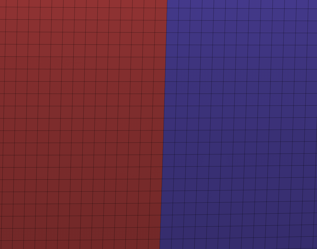
Most UV pack algorithms will only rotate the UV shells by 90°. This is done, to reduce the visibility of jagged lines. The reason for the jagged lines has to do with the fact that a monitor pixel has four sides (rasterisation). Having the UV shell follow the flow of one of the these sides, that being 90°, 180°, 270°, 360° reduces the effect of jagged edges. Anti-aliasing can also help reduce this issue, but it’s best to combine both of these methods.
90° snap texture result example (without the help of anti-aliasing)
45° snap texture result example (without the help of anti-aliasing)
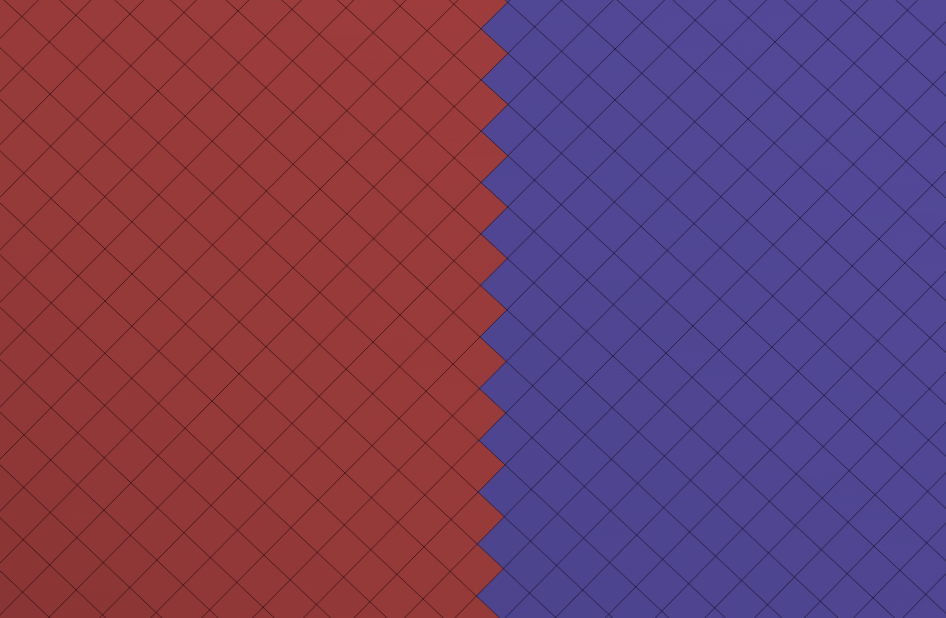
With higher resolution textures, this is less of an issue, and in rare situations there can be reasons why one would want to rotate UV shells by more or less than 90°, but in most cases one should stick to 90° rotations.
Keeping UV shells at 90° angles can also make texturing easier.
Mirroring UVs
Before UV unwrapping, one has to decide how to proceed with mirrors. One can apply mirrors before UV mapping or at the end right before export.
Applying the mirror at export will double the available texture space for UV mapping, as only the right / left side of the model needs to be mapped and the other side is then stacked on top of those shells at export. This then in return means that one can use less or smaller resolution textures, or simply have a better texture resolution.
There is one mayor issue with mirroring UVs though, both sides will look the same, which can make the textures look less interesting. Procedural textures especially stand out in a bad way when mirrored.
For this reason, applying the mirror beforehand is often needed for specific designs or to make textures look more natural around the midline. For example, one wouldn’t mirror the UVs of a character’s shirt if it has some text on it, or when the character’s face has a scar. A disadvantage of applying the mirror before UV mapping, is that it’s a lot harder to make changes on the model from that point on and making a backup before applying mirrors is essential.
The solution is quite simple, one has to mix it up. Objects that connect at the middle and mirror from left to right should generally not have stacked UVs, but when the mesh is farther away from the middle, stacked UVs are more ok. This obviously depends on the texture map budget and if it’s important to have only a few and lower resolution textures, then one should probably mirror as much as possible. Another interesting option is to only stack the UVs of parts of the mesh of an object. One could run UV splits around the shoulder joint of a jacket, apply the mirror, and then unwrap the center part and the right arm. One would then use some stacking tool to stack the UV shells of the left arm onto the right arm. (This method, however, comes with its own set of problems and should only be used if UV space optimization is key.)
Just don’t get too paranoid about mirroring, as when looking at characters in game from normal viewing distances, it’s hardly noticeable that the UVs were mirrored, so saving the texture space is mostly the better option. And for the film industry, there is absolutely no reason to ever stack UVs.
Tip
It’s good practice to try to keep an edge loop running down the center line, even if one doesn’t want to mirror the UVs, so one can later on change one’s mind on it (this matters less for hard surface objects and is more important for deformation objects that have complex topology).
Some Helpful Things for Mirroring UVs :
- A good workflow is to apply mirrors for all objects and then to stack UVs with tools that search for same UVs and stack them
- Don’t place seams for both sides. Either place them before mirroring or symmetrize the topology, so both sides have the same seam
Margin & Padding
Padding is an important component of UV mapping, it prevents texture bleeding, which will be visible as seams on the model. Proper padding is also important for getting nice bevels when baking.
When one refers to margin, one is talking about the distance between every UV shell, while padding refers to the distance between all the shells and the texture borders.
The amount of padding depends on the texture resolution. It also depends on how much downresing will happen. If the highest resolution of the texture is 4k and there is a low setting which downreses / mips the texture to 256px, then more padding is needed. The way the texture will be viewed also important, if it’s a roof tile on an atlas environment sheet, that’s viewed from extremely intense angles and will be mipped / filtered to hell, then more padding is generally good.
Recommended paddings & margins
Padding is per shell, so a padding of 2px will result in a 4px distance between 2 shells.
Texture Map Size Recommended Padding 4096px 16px - 32px 2048px 8px - 16px 1024px 4px - 8px 512px 2px - 4px 256px 1px - 2px 128px 0.5px - 1px
It’s totally fine to have a margin of 1px as there can’t be any bleeding onto other UV shells at the edge of the texture. The only reason one would want more margin, is to make texturing easier, or to make the UV unwrap look better.
Baking software often adds a margin of its own, if your baking software does this, disable it.
Straightening UV Shells
There are three reasons why one would want to straighten UV shells; to optimize texture space because straightened shells can be fitted together more tightly, to make texturing easier (like specific texture patterns or hand painting methods) and to make the UV unwrap look more beautiful.
Straightening UVs comes at a cost though, a small distortion. This distortion really isn’t that bad, but is why straightening shells is very popular in the game industry, and less needed in the film industry, as texture space isn’t a problem there.
A simple Blender add-on that can do this is UV Squares (it needs quad topology to work). Here’s a video by Josh showing it in action:
Texel Density
Texel Density Videos and Articles
These 2 videos are the only ones you really need to watch:
Here some more:
Texel density describes the amount of texture resolution on a mesh. In the same way that pixels are the smallest unit of a screen, texels (short for texture elements) are the smallest unit of a texture. The bigger the UV shell, the more texel density it has and the more texel density, the higher the resolution of that area.
In general, the texel density should be consistent across the entire model. Different meshes with varying texel densities next to each other, will be very noticeable. That said, there are times, where one can break this rule.
Different meshes with varying texel densities next to each other
For example, let’s say we make a character like Samus, and we know, that there will be many close up shots of the face in addition to the face being an area where the eye often gravitates to, then it can make sense to increase the texel density for that area. And because Samus (suit) only shows skin down to the neckline, the shift in texel density won’t be too noticeable. One could quite literally add in some sort of neck choker just to hide the texel density shift.
Different texel densities across multiple UV shells that are on the same mesh, can cause problems while texturing with procedural materials, for example.
Here’s a chart of different texel densities, how they are calculated and what they are used for:
| Texture Resolution | Divided by Standard UDIM Unit (Project dependent) normally 100cm (1m) | Texel Density in px/cm or px/unit | Used For | Density Category |
|---|---|---|---|---|
| 128px | ➗ 100cm 🟰 | 1,28 | Strategic Camera | 🟥 Low |
| 256px | ➗ 100cm 🟰 | 2,56 | Strategic Camera | 🟥 Low |
| 512px | ➗ 100cm 🟰 | 5,12 | Third-Person Camera | 🟨 Medium |
| 1024px | ➗ 100cm 🟰 | 10,24 | First-Person Camera | 🟩 High |
| 2058px | ➗ 100cm 🟰 | 20,48 | First-Person Weapon and Arms | 🟩 High |
| 4096px | ➗ 100cm 🟰 | 40,48 | First-Person Weapon and Arms | 🟩 Very High |
| 8192px | ➗ 100cm 🟰 | 80,96 | 🟩 Ultra High |
Texel density consistency between different artists and models in the scope of a project or game is key. The trick to staying consistent but also varying the texel density is to split up the environment into different priority / density groups, as seen in these images:
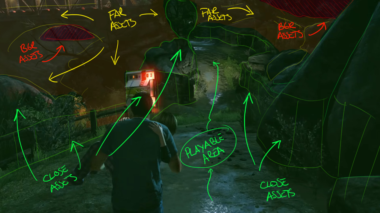
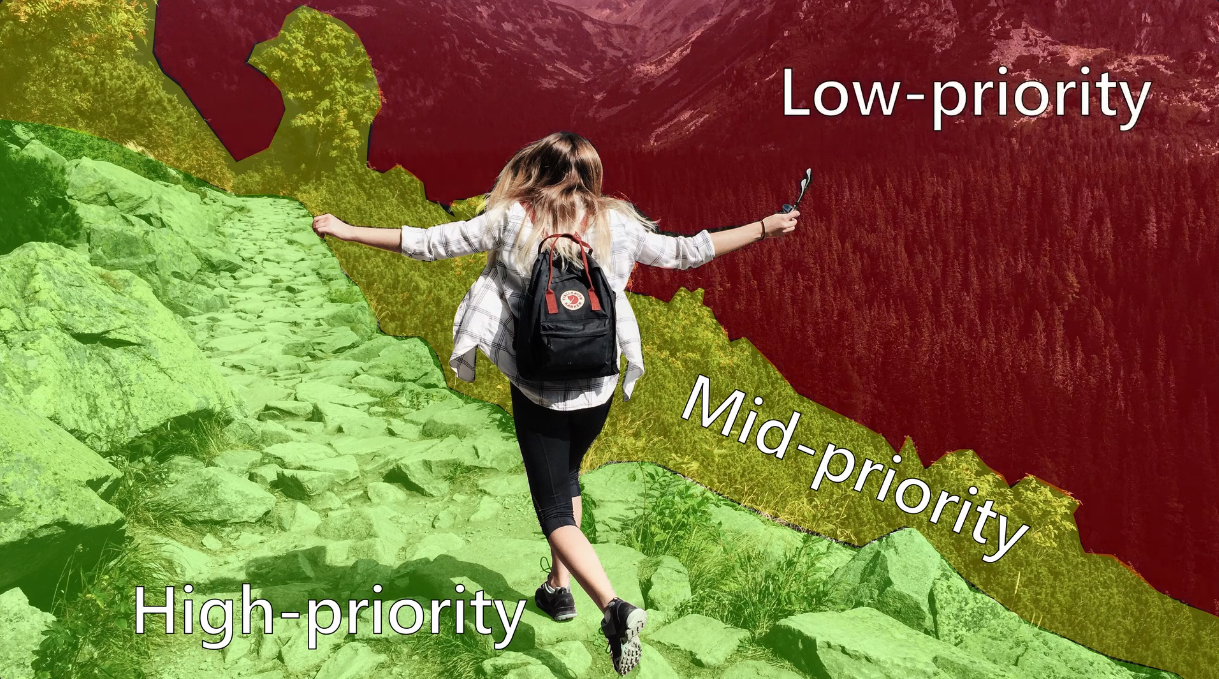 images by Leonardo Iezzi and Nicky Cry
| Priority / Density Group | Description |
|---|---|
| 🟩 High 🟩 | Places the player can easily get close to |
| 🟨 Medium 🟨 | |
| 🟥 Low 🟥 | Background + Far away assets |
This concept doesn’t only apply to environments, but can also be used for characters, where areas like face, hands and weapons have an increased texel density.
All the things that affect the choice in texel density are :
- Camera perspective
- Distance from camera to asset
- Hardware goal
- Art style
As discussed before, the size of the UV shell affects the texel density, so scaling up or down a UV shell, will increase or decrease the texel density for that UV shell. Of course, in an actual pipeline, this isn’t done by hand but by tools.
If you’re using Blender, you should first make sure that all the low objects have their scale transform applied, as that will mess with the texel density.
After UV unwrapping, all the objects will have the same texel density. The next step is adjusting the texel density, for that the add-on Texel Density Checker is used. For information on how to use that add-on, look at the videos at the top of this Texel Density section, or take a look at their short GitHub documentation
**Some more things worth mentioning: **
- It’s also essential to always scale UV shells evenly along all axes, not doing so will result in distorted textures.
- The simplest way to see texel density inconsistencies, is with the help of UV checker maps.
- If you notice, that you screwed up the scaling of some of your shells, then there are some easy ways to fix it. Firstly, re unwrapping the affected UVs will give them the same scale again. A much better way of doing it, that doesn’t require re unwrapping, is by selecting the affected UV shells in the UV editor and clicking
UV > Average Islands Scale. - If you notice that you simply can’t get things to look crisp with your texture budget, even after optimizing everything, then as a last resort one can start sacrificing the detail of some UV shells to have more space in return to scale up those UV shells that really need it. This isn’t a very professional way of doing things and should be used as a last resort
UV Packing
UV packing is the last step of the UV process, but occasionally packing beforehand can be helpful, to get a feel of what still has to be done. The goal with packing is to fit all UV shells as densely together as possible, so all shells can use more of the UV space and have more texture resolution.
In the game industry, UV packing is done with packing algorithms. For the film industry this isn’t always the case though, here’s a video by Flipped Normals explaining the benefit of packing by hand.
Blender has a built-in packing algorithm, but its functionality is quite lackluster (UV > Pack Islands). Clicking on it’ll open a menu with some packing customization options.
What I recommend using, instead, is UV Pack Master. It’s able to pack much more efficiently and has many more vital packing options. It has a free and paid version, but I think the paid version is well worth it. More on how to use UV Pack Master here.
Good UV Unwrap Examples
To-Do
UV Pack Master
UV Pack Master has quite a lot of settings that help to achieve the perfect pack. The official documentation is here.
Some of the most important things are
General
- Use Overlap Check to find overlapping UVs (this won’t find overlapping faces of the same UV shell)
- Increase Precision to prevent packing errors like overlaps
- Enable Heuristic Search for better pack results (but slightly slower packing speed)
Stacking UV Shells
If the model has many repeating parts, stacking identical UVs on top of each other, can save a lot of space. Even if some vertices of these repeating parts move a bit, they can still be stacked by increasing the similarity threshold. A lot of stacking work can be avoided by applying some mirrors right before export instead of before UV mapping.
To select which UV shells to stack, one can link select a shell and use Select Similar or simply select everything, then one uses Align Similar. Adjust the Similarity Threshold until the desired shells are stacked.
Overlap Detection Mode is responsible for keeping the stacked shells together while packing. Switch between Exact and Any Part depending on the situation (Lock Overlapping does the same).
Using Stack Groups can also be helpful.
If more complex stacking functionality is needed, then Group By Similarity is for you. Look into the documentation for information on that.
Add New Shells to an Already Packed UV
Select all the new shells and use Pack to Others instead of Pack.
Pack UVs Across Multiple UDIMs
Enable Custom Target Box click Edit Target Box and use the arrow buttons to navigate between UDIMs. When the desired UDIM is selected, select all shells you want on there and Pack.
Padding between UVs
Don’t use the main Margin option, instead enable Pixel Margin and use those margins and paddings instead. For help on what values to use, look at the Margin & Padding section.
Packing in Custom Aspect Ratios
Sometimes the texture needs to be other aspect ratios than 1x1 (like D.VA’s mech texture). In those cases, one tell the packing algorithm to pack in different aspect ratios.
To do this, add the texture with the aspect ratio you’re aiming for. Then enable Non-Square Packing and click Adjust Islands To Texture. More on this here.
Zen UV
Zen UV is a wonderful UV unwrapping tool, I’ll cover it at some point. Here’s the channel of the add-on’s creator.