─────────
Visual
─────────
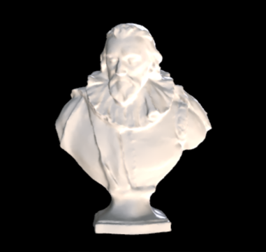
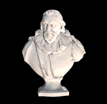
Ambient Occlusion
[Wikipedia] - [Polycount] - [Unreal Engine Doc] - [Unity Doc]
Ambient occlusion (AO) is a rendering technique used to calculate how exposed each point in a scene is to ambient lighting. It shows subtle variations in lighting as well as shadows and helps one’s eyes detect surface details that would otherwise be washed out or unnoticeable.
Ambient Occlusion Info
- Softens the overall lighting in your scene
- Adds depth
- Can be used as a budget ray traced occlusion
- Requires high-resolution light maps to look good
| Ambient Occlusion Off | Ambient Occlusion On |
|---|---|
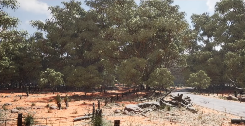 | 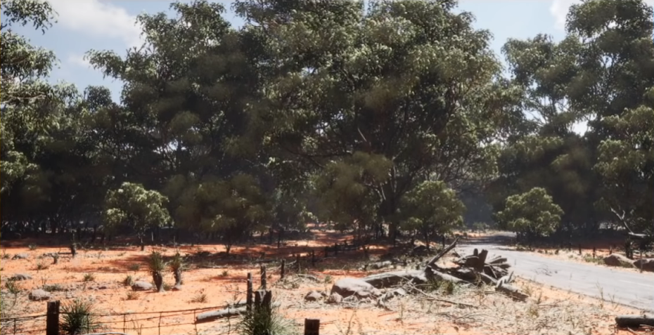 |
 |  |
 |  |
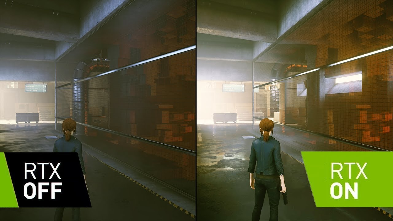
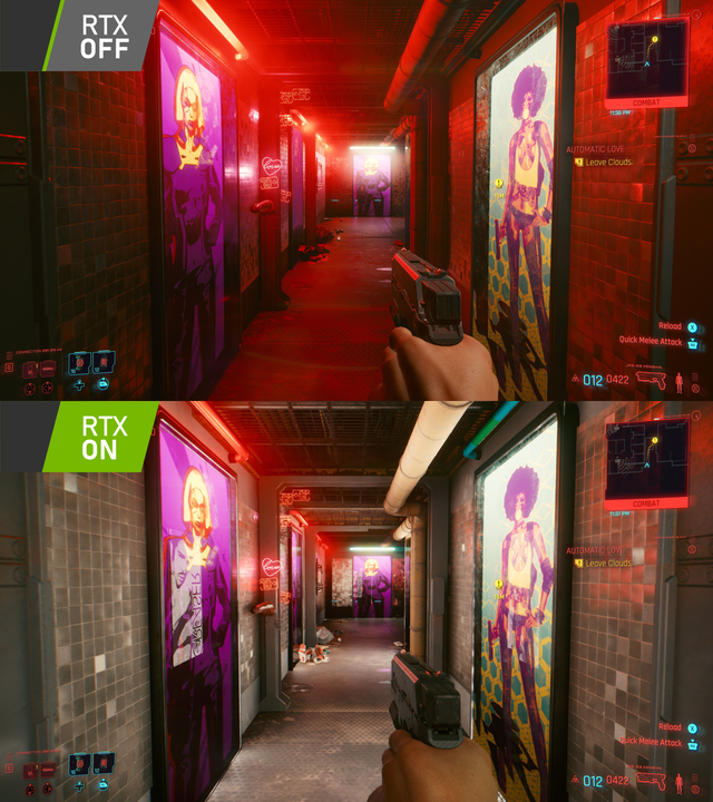
Ray Tracing
[Wikipedia] - [Unreal Engine Showcase] - [Unreal Engine Doc (real-time)] - [Unreal Engine Doc (hardware)] - [Unity Doc] - [Ray Tracing in One Weekend] - [Ray Tracing Gems Series]
Ray tracing is a rendering technique that simulates the physical behavior of light rays. It allows accurate rendering of things like shadows, reflections, highlights and bounced light. However, ray tracing doesn’t make everything better, and sometimes it’s good to turn off ray traced shadows, lights and only keep ray traced reflections on.
There are two types of ray tracing: Real-time ray tracing (games industry) and hardware ray tracing (film industry).
Ray tracing is a broad term that consists of many smaller things like:
- Ray Traced Shadows
- Ray Traced Reflections
- Ray Traced Lighting
- Ray Traced Ambient Occlusion
- Ray Traced Global Illumination [1][2]
- Ray Traced Translucency
Graphics Card Specifications
For Nvidia cards it only works on Nvidia RTX and some Nvidia GTX series graphics cards (all their graphic cards with DirectX have ray tracing support)
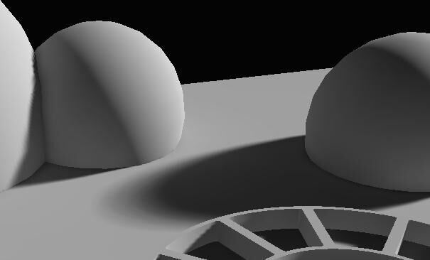
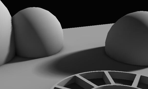
Ray tracing off vs. on:
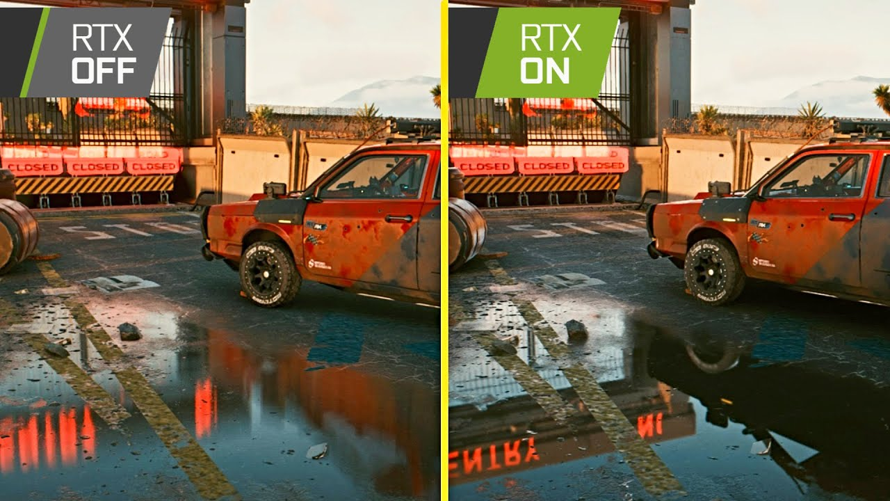
On the flipped side, here’s an example of ray tracing making the lighting and shadows look way worse:
This doesn’t mean that ray tracing in its nature makes lighting and shadows worse, but rather adding ray tracing into a scene that wasn’t designed with ray tracing in mind won’t yield good results. It’s important for the environment artists to have direct previews of how the scene will look like with ray tracing on. And potentially there needs to be two different presets for ray tracing on and off.
Real-Time Rendering
[Real-time Rendering Book (4th Edition)] - [Real-time Rendering Book Digital Summary (4th Edition)]
Subsurface Scattering
Subsurface scattering (SSS), also sometimes referred to as the skin shader, is a rendering technique, which allows for objects to appear more alive by scattering light more realistically inside themselves. Though subsurface scattering mostly has a reddish glow, the color totally depends on what is on the SSS Color Map🗺️ as well as the light source color. For the render engine to properly scatter the light, it also needs to know the thickness of each area on the model. For that, the Thickness Map🗺️ is used (a map which also has other uses besides subsurface scattering). The SSS Color Map🗺️ is also sometimes complemented with an SSS Control Map🗺️.
Real objects can either absorb, scatter or ??? (To-Do) light rays. To recreate this in 3D, subsurface scattering maps are used in combination with thickness maps.
Theory behind real life subsurface scattering (Transparency & Translucency)
When traveling in an inhomogeneous medium like air or translucent materials, light can be absorbed or scattered.
When absorption occurs, the light intensity decreases and the direction of the ray doesn’t change.
Objects that absorb light
When scattering occur, the ray direction changes randomly and doesn’t change its intensity.
Objects that scatter light
- Dirty water
If there is no scattering and the absorption is low, rays can pass directly through.
Objects that don't scatter light with low absorption
- Clear water
The further light travels in such a medium / material, the more it’s absorbed and scattered. Therefore, object thickness plays a large role in how much the light is absorbed or scattered
Examples of SSS in action
Ears are thin >>> Low light ray absorption = Light is very visible through ears

Objects where SSS is vital
- Fleshy characters (any character or creature)
- Wacs
- Marble
- Milk
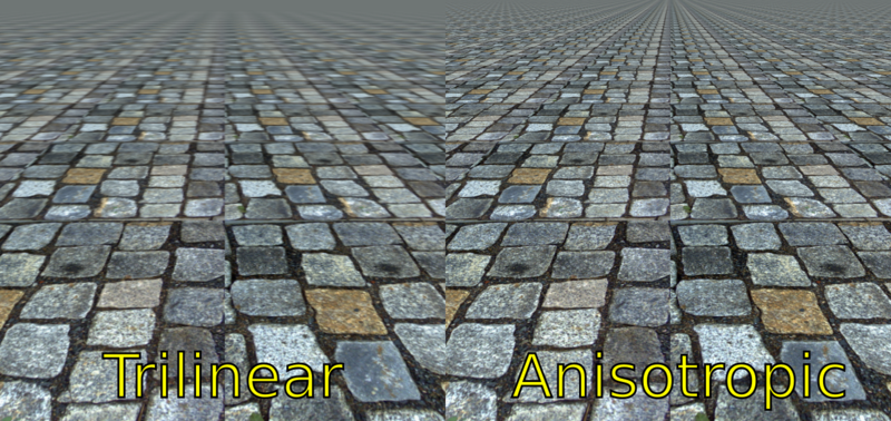
Anisotropic Filtering
To-Do: Explain better
Anisotropic Filtering (AF), is a rendering technique that enhances the image quality of textures on surfaces that are at oblique viewing angles with respect to the camera. Like bilinear and trilinear filtering, anisotropic filtering eliminates aliasing effects.
Screen Space Refraction
- Adds local reflections to the objects
- Helps Glass, plastic, water, and other transparent/translucent materials.
- Similar to screen space reflection. Screen Space Reflections and Ambient Occlusion aren’t compatible with Screen Space Refraction. And are disabled on surfaces that use it.
Screen Space Reflection
A rendering technique for reusing screen-space data to calculate reflections. Used for more subtle reflections like wet surfaces or puddles.
Caustics
Bloom
-
Bloom / light bloom (not to be confused with glow/emission) is a rendering technique to reproduce artifacts of real-world cameras. It produces fringes or feathers of light extending from the borders of bright areas in an image, contributing to the illusion of an extremely bright light overwhelming the camera or eye capturing the scene.
-
Even tough bloom is most apparent around emissive objects, it can just as well happen with normal light sources
Motion Blur
- Portrays the illusion of speed or movement blurring the objects
- Tends to remove temporal aliasing effects
- Used as a real-time filter, for animation renders and even still renders
- Not having Motion Blur on can lead to more eye strain, but can give you motion sickness
- It can also increase the visual fidelity
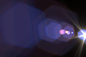
Lens Flare
ToDo
Volumetric Effects
ToDo: add in term Volumetric Sampling
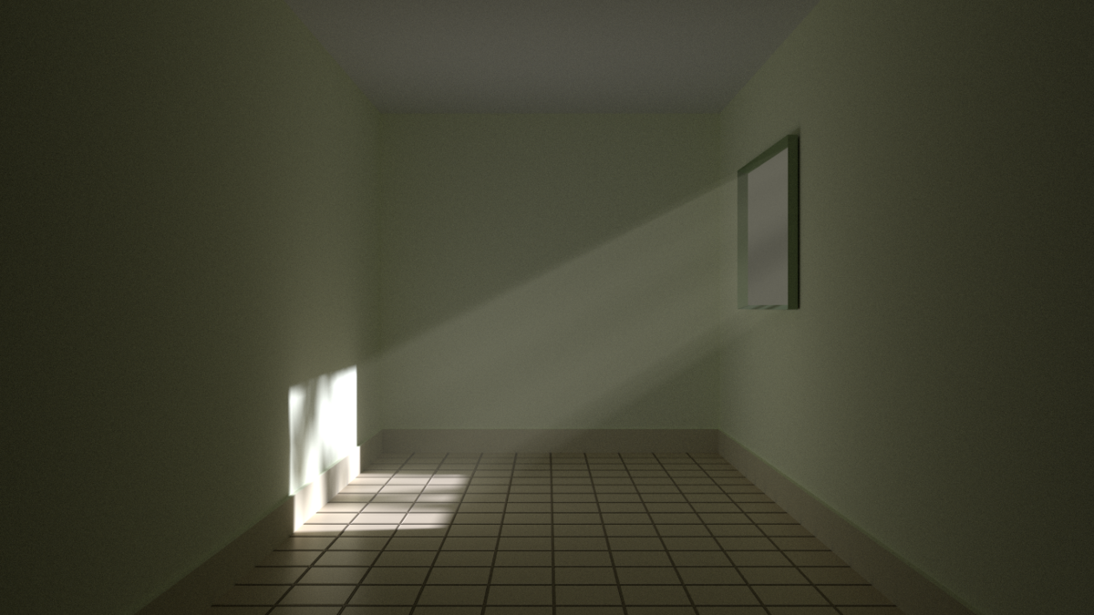
Volumetric Lighting
Volumetric lighting or God Rays lets beams of light shine across the environment.
Volumetric Fog
Volumetric Fog is used for
- Fog
- clouds
- dust
- smoke
- Or any airborne material capable of partial occlusion
Volumetric fog has a great synergy with volumetric lighting.
ToDo: Add image
Chromatic Aberration
To-Do: Restructure
- In real life chromatic aberration occurs when a lens fails to focus all the colors into a single point, causing an ever so slight color shift on the edges of some objects
- A color fringing or distortion
- Basically the R, G and B channels are shifted to the left or right. The shift amount and what channels are shifted can be tweaked
Depth of Field
Blurs out things that are farther away from the focus point. The distance at which the effects starts and ends at, as well as the fall off, can all be adjusted in the render or game engine’s settings. Sometimes it’s even possible to set multiple focal points.
DLSS and FSR
- DLSS stands for Deep Learning Super Sampling (Nvidia GPUs)
- FSR stands for FidelityFX Super Resolution (AMD GPUs)
Both DLSS and FSR are basically the same thing, just developed by different companies. They are an image upscaling technology which use deep learning to upscale lower-resolution images.
Anti-Aliasing
Anti-aliasing (AA) removes aliasing effect. Aliasing is the appearance of jagged edges in a rasterized image (image rendered using pixels). Samples the pixels around the edges and uses them to blend away the appearance of jagged edges.
Blend Modes in 3D Software
ToDo: Restructure
Blend methods apply to every software (some have more or less modes). Every texture has to have a blend mode, the most common one being opaque. Blend Modes describe how the output of the current material will blend over what is already being drawn (rendered) in the background.
- Black = invisible & not rendered
- White = visible & rendered
Opaque Blend
Surface through which light neither passes nor penetrates. The previous color will be overwritten and alpha is ignored.
- Cheapest blend method
Opaque Blend Examples
- Plastics
- Metals
- Stone
- Wood
Masked Blend & Alpha Clip
Used to make some parts invisible and others visible. The invisible parts aren’t rendered at all. Only needs black and white, however if gray values are in the control texture a clip threshold value (which is per default set but can be changed) decides what counts as black and what as white.
Masked Blend & Alpha Clip Examples
- Fence
- Chains
- Net
Translucent Blend & Alpha Hashed
Used for objects that require some form of transparency. By taking advantage of the full range of an opacity control map, it can make objects be and opacity level.
- Can produce noise
- Most expensive blend mode
Translucent Blend & Alpha Hashed Examples
- Thin cloth
- Jellyfish
- Nylons
- A lot of female clothing
Additive
Takes the pixels of the Material and adds them to the pixels of the background (Like PS Linear Dodge (Add)) No darkening, since all pixel values are added together.
Multiply & Modulate
Multiplies the values of the Material against the pixels of the background.
Object Properties
Transparent
- With transparent objects, almost all light passes directly through them.
- One can clearly see what’s behind transparent objects
Transparent Examples
- Air
- Water
- Clear glass
- Plastic wrap
Translucent
- Translucent objects allow some light to travel through them.
- Often one can’t see what’s behind a translucent object but
Translucent Examples
- Frosted glass
- Sunglasses
- Notebook paper
- Lampshade
Transparency, Opacity & Alpha
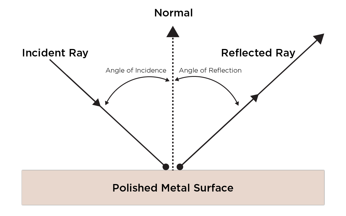
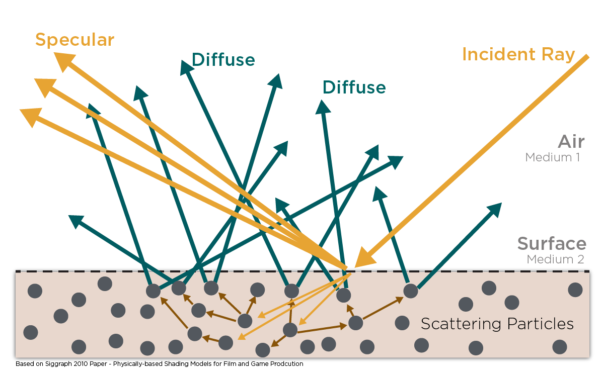
Light Ray
- In air light rays travel as straight lines
- A light ray that hits a surface is called the
incident rayand the light that bounces off a surface is called thereflected ray - When the light ray hits an
opaque surfacethereflected angleis thesameas theincidence angle - When a light ray hits opaque surface one of two events occur:
- Incident light ray hit surface and
bounces offin the same angle(reflected light) - The light ray
passes throughthe surface in a straight line(refracted light)
- Incident light ray hit surface and
- Absorption of the light ray doesn’t occur on the material surface
Objects that reflect light
- Polished metal
- Glass
- Water
Objects that reflect light
- Lenses
- Prism
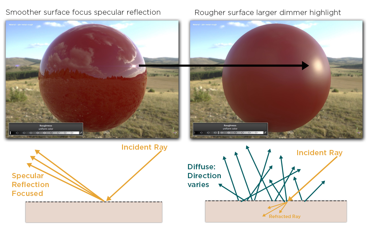
Specular Reflection
- The more planar the surface is, the more the incidence angle equals the reflected angle (law of reflection)
- Most surfaces are irregular
- Rougher surfaces have
larger highlightsand aredimmerandless reflective - Smoother surfaces are
brighterandmore reflective
Examples:
Smoother Objects
- Polished metal
- Glass
- Water
Rougher Objects
- Concrete
- Wood
- Leather
Diffuse Reflection
- Diffuse reflection is light that has been refracted
- Light ray hits a surface, enters the object, is scattered multiple times and finally is refracted out of the object at the same point it entered the object
- Most diffuse materials have high absorption so for the light to leave the object it can only travel (scatter) short distances within the object
- Materials with both high scattering and low absorption are called translucent or participating materials
- The outgoing direction of the ray is fairly independent of surface roughness and the incident direction
- Surface irregularities are referred to as roughness, smoothness, glossiness or micro-surface
Examples for diffuse objects:
Objects with high scattering and high absorption
Objects with high scattering and low absorption
- Smoke
- Milk
- Skin
- Jade
- Marble
- Fog
Physically based rendering
[Allegorithmic’s PBR Guide Part 1] - [Allegorithmic’s PBR Guide Part 2] - [Physically Based Rendering: From Theory To Implementation (4th edition)]
To-Do:
Physically based rendering or in short, PBR is …
Bokeh
Noise
ToDo: Voronoi, Perlin, Musgrave https://en.wikipedia.org/wiki/Voronoi_diagram https://cfbrasz.github.io/Voronoi.html https://en.wikipedia.org/wiki/Perlin_noise http://kitfox.com/projects/perlinNoiseMaker/
Fireflies
Global Illumination
Shadow Mapping
Radiosity
ToDo: And other types of rendering techniques: https://3d-ace.com/blog/different-rendering-techniques/
Index of Refraction
ToDo: Index of refraction (IOR) also referred to as refractive index, is a …
HDR & SDR
─────────
Topology
─────────
Polygon, Vertex, Edge, Triangle, Quad, N-gon
A polygon is a face / plane consisting of 3 or more edges (sides). Whenever two edges meet, a vertex (corner) is created.
A polygon with exactly 3 vertices is a triangle also referred to as a tri, with 4 it’s a quad and anything more than 4 is referred to as an n-gon (because in mathematics “n” is used to denote every possible positive value). In theory, a triangle is a 3-gon, and a quad is a 4-gon, but no one actually calls it that.
A tringle will always be planar (flat) by the nature of only having 3 vertices, quads and n-gons however can be non-planar, but it’s desired to have them be as planar as possible, which brings us to the next point.
Almost all render and game engines will convert quads and n-gons into triangles at render time. This is why it’s important for quads and n-gons to be as planar as possible, as triangulating them can change the silhouette and shading when they aren’t flat. More on that in the triangulation section.
In mathematics polygons are allowed to intersect themselves, in 3D however not.
Triangulation
Triangulation, also referred to as tessellation, is the process of the converting quads and n-gons to triangles. In the case of a quad, for example, there are two ways of triangulating it. The way in which quads and n-gons are triangulated depends on the algorithm that is used, and thus can differ between software and even versions of the same software.
As an artist, working on a character’s final retopology, one wants to make sure that what one is seeing, will look exactly like that in the game engine. Thus, it’s important ToDo
There are two ways of getting a consistent triangulation results, either one triangulates the mesh at export of the modeling software or one gets familiar with the triangulation algorithms as some software like Blender lets the user choose which algorithm to use.
All prominent triangulation algorithms. (Some of these like Delaunay have sub variants)
| Triangulation Algoritm | How good is it? | Pros | Cons | How it works |
|---|---|---|---|---|
| Delaunay triangulation | - Avoids thin triangles (sliver triangles), by maximizing the size of the smallest angle | |||
| Ear clipping triangulation (Ear trimming) | ||||
| Minimum-weight triangulation (Shortest diagonal) | Split the quads along their shortest diagonal. | |||
| Longest diagonal triangulation | - Can be good for cloth simulations. | Split the quads along their longest diagonal. | ||
| Point-set triangulation | ||||
| Random triangulation | Very inconsistent with bad results, but the fastest of the bunch. | Triangulation speed hardly matters, making this useless. | Although this isn’t used anywhere, it’s the most basic kind of triangulation method. |
What software uses which algorithms.
| Software | Triangulation Algoritm |
|---|---|
| Blender | Ear clipping |
| Maya | |
| Unreal Engine | Delaunay triangulation |
| Marmoset Toolbag | |
| Unity |
The most popular triangulation algorithm is. A full list of all the algorithms can be found here
https://en.wikipedia.org/wiki/Delaunay_triangulation http://www.polygontriangulation.com/2018/07/triangulation-algorithm.html https://ianthehenry.com/posts/delaunay/ https://paulbourke.net/papers/triangulate/ https://www.cs.cmu.edu/~quake/triangle.html https://docs.blender.org/manual/en/latest/modeling/modifiers/generate/triangulate.html https://polycount.com/discussion/105479/question-about-baking-with-triangulation https://discourse.techart.online/t/when-to-triangulate-in-a-pipeline/4654
“tri-stripping method”
“Yes, the resulting triangulation would suck. The Delaunay triangulation has many interesting properties: angles aren’t too bad, triangles aren’t too many, neighbouring triangles also, etc.”
“The Delaunay triangulation seeks to avoid this. The algorithm picks a triangulation that maximizes the smallest angle, which avoids thin triangles as much as possible and so gives better error terms.”
“You don’t always have to, but xNormal will triangulate before calculating maps and generally each program will triangulate a little differently. If you don’t triangulate before baking, it’ll mean the model it calculates the maps for will have different face normals than the one you triangulate later in Max. If you don’t triangulate prior, and notice strange anomalies with normal maps(single faces with weird black spots), this is what causes that.”
I use the word “can” as the result can be quite random. A quad can be triangulated in two different ways and while the software will use an algorithm to determine the best way to triangulate a polygon to keep it as planar as possible, it’s often not an acceptable result. This can be especially noticeable with low poly meshes. To get clean results one first makes sure to In this case the artist will manually triangulate polygons which
Almost all render and game engines will convert n-gons and quads into triangles at render time.
Triangulation, also referred to as tessellation, is the process of the converting faces to random even triangles.
ToDo(things to cover):
- Manual vs automatic triangulation and how cutting faces into trinagles differently can make a big difference
- Triangles in relation to game engines
- UE5 Nanite
Subdivision Surface
Subdivision Surface (also referred to as Subdivisions, Subsurf and SubD) is a basic algorithm which adds poly density by dividing every face on a mesh into 4 smaller faces. As a result, it’ll work much better with nice quad-based topology. Something else to take into regard, is that the times 4 is and exponential addition, so the poly count can quickly get out of hand if to many level of subdivision are added, which can make the software laggy or result in a crash.
There are many different variants of the subdivision surface algorithm and can be split into two categories. The Interpolating schemes match the original position of the vertices, while the approximating schemes modify the position of the vertices, allowing for stuff like smooth surfaces.
The most common one is the Catmull and Clark algorithm. It nicely smooths the surface more and more with every subdivision level and is used in pretty much every 3D software.
Subdivision make the mesh harder to work with and are mostly destructive, so software often use dynamic subdivision methods which can be edited and disabled on a whim. Other software like ZBrush opt into a more complex method where changes made on every subdivision level are stored individually allowing for sculpting of fine details like pores on a high subdivision level, while being able to go back down to a lower level to modify the broader shape, while keeping the small detail intact.
Poles
There are two types of poles, N-Poles (3 edges) and E-Poles (5+ edges). More about poles on the topology page.
A pole is a set of edges that merge into a single vertex. Avoiding poles with six or more edges on curved surfaces is something that you should incorporate into your modeling workflow. It’s best practice to try to avoid poles when modeling.
Faces
- Triangle, Tris, Polygon: 3 vert face
- Quad: 4 vert face
- Ngon: 5+ vert face
Backface Culling
To-Do
Convex & Convex Hull
Convex is means (ToDo). A convex hull is a mesh that wraps around another mesh in the most optimal way.
Convex Hulls are used for
- Collisions
- Physics calculation boundaries, for hair for example
- Baking cages
Chamfer
A corner with one edge is a hard edge, with 2 edges a chamfer and anything more than 2 is a bevel. Chamfers mostly have a ~45° angle.
LOD
To-Do
LOD’s (Level of Detail) …
Smoothing Split
A Smoothing split, also sometimes referred to as a shading split, is when ToDo (include terms “soft edge”, “sharp edge” and “hard edge”).
Software like Maya and 3ds Max work with smoothing groups to create smoothing splits. With smoothing groups, one basically creates many smoothing groups which are a selection of one or more faces, and wherever the smoothing groups meet a smoothing split is created. Blender’s approach is quite different, but the result is the same. Instead of creating smoothing groups that create smoothing splits, one directly creates the smoothing split, by marking edges as sharp. This allows for more control, as one can have individual edges with smoothing splits, instead of being limited to full faces (not something that’s necessarily useful, though).
Some related articles
UV & UV Shell & UV Island
ToDo UV stand for horizontal and vertical.
─────────
Textures
─────────
Bit Depth
[Wikipedia] - [Polycount] - [Photoshop Doc]
Bit depth explanation (videos)
Bit depth explanation
Bit depth (Color depth) determines how much color information an image can store, which directly influences the dynamic range the image can have.
It’s often good to render or bake images with higher bit depth than needed, and later in the process convert them to a lower bit depth. The trade-offs with higher bit depths are increased render times and bigger file sizes.
Bit Depth Math
The most common bit depths are 8bit, 16bit, 24bit and 32bit. Let’s take 32bit for example, 8 of the 32 channels represent red, 8 channels green, 8 channels blue and lastly 8 channels for alpha. This means that just by looking at the bit depth, one can deduce whether the image has alpha or not. If the image didn’t have alpha, those 8 channels for alpha would fall away and one would have a 24bit image.
- 6bit RGB (2,2,2)
- 8bit RGBA (2,2,2,2)
- 12bit RGB (4,4,4)
- 16bit RGBA (4,4,4,4) or (5,6,5)
- 24bit RGB (8,8,8)
- 32bit RGBA (8,8,8,8)
Max amount of unique values per channel:
1bit image (Integer)
2 Tone Values 🟰 Black (0) and White (1)
8bit image (Integer)
256 Tone Values ➡️ 256 Reds ✖️ 256 Greens ✖️ 256 Blues 🟰 16.7 Million RGB Values
16bit image (Integer / Float)
65,536 Tone Values ➡️ 65,536 Reds ✖️ 65,536 Greens ✖️ 65,536 Blues 🟰 281 Trillion RGB Values
32bit image (Integer / Float)
4,294,967,295 Tone Values ➡️ …
So 16 bit is 250 times bigger than 8 bit and 32 bit is 15 million times bigger than 16 bit (exponential growth). Though the file size gets progressively bigger, it doesn’t increase by that margin.
Human Perception of Bit Depth
Humans can only distinguish between 2 ~ 10 million colors, so we can’t even see all colors of 8bit. This means that an image exported in 8bit or 16bit will always look identical. The only advantage in using anything above 8bit is for editing photos and only for the process of editing and not the export. For 2D artists 8bit will always be enough and most drawing software doesn’t even support more than 8bit.
Banding
Banding artifacts are caused by a lack of precision with 8bit normal maps. There aren’t enough color values to accurately represent subtle differences between the high poly and low poly surfaces, which results in stair stepping artifacts.
Atlas & Trim Sheet
To-Do
Dithering
Adds noise to combat banding. So Dithering is mostly only used with low bit images. Dithering can be done by adding a noise filter in Photoshop.
Tangent Space
Normal maps can be tangent-space or object-space. World-space is basically the same as object-space, except it requires the model to remain in its original orientation, neither rotating nor deforming, so it’s rarely ever used. Always use tangent space for the normal map, however object space normal maps can be useful as a utility mask for texturing. The object space Normals maps are easily spotted, they look like orange normal maps.
Handedness
Handedness has an influence over things like normal maps, object transforms, rigs and animations.
Normal maps can either be in the Open GL or Direct X format. To switch between the formats, one can invert the textures green channel, check some invert button in a software or manually edit the normal map in Photoshop. One should however always try to stick with the Open GL format as is make the most sense visually and is broadly accepted as the industry standard. Funnily, enough Unreal uses the inferior Direct X format. To fix one’s normal maps non-destructively in Unreal, one can simply enable the “Flip Green Channel” in the texture settings.
Here’s a list of which software uses what format (some software allows for switching between Open GL and Direct X):
| API | Handedness | Cords | Software |
|---|---|---|---|
| Open GL | Right Handed | Y-Up | Marmoset Toolbag, Substance Painter, Maya, Houdini, Modo |
| Open GL | Right Handed | Z-Up | Blender, 3ds Max, CryENGINE |
| Direct X | Left Handed | Y-Up | Substance Painter, ZBrush, Unity, Cinema 4D, Light Wave |
| Direct X | Left Handed | Z-Up | Unreal Engine |
As mentioned before, handedness can also influence objects, if an imported object is rotated incorrectly, then it’s probably because the source and destination software have a different handedness.
The X coordinate is in all software the right vector (Left / Right). The Y and X coordinates can either be the forward vector (Forward / Backward or Backward / Forward) or the up vector (Up / Down or Down / Up).
It’s important to use the same space for an assets and its textures. When working with software that has different spaces, this can be done by switching channels at export.
Mipmaps
To-Do
Tangent Space
To-Do https://marmoset.co/posts/toolbag-baking-tutorial/
Rasterization & Vector
─────────
Animation
─────────
To-Do
Apex and Peak
To-Do
Bone Head, Tail and Body
To-Do
─────────
Baking
─────────
Floaters
Floaters are loose detail pieces that float above the surface of a mesh and are baked down into the normal map. This creates the illusion that they are connected with the mesh they hover above. A boolean cut floater for example can save a lot of time because one doesn’t actually have to do a boolean cut and can quickly duplicate the piece along the mesh surface without having to integrate it into the topology.
Low and High Poly
ToDo
(in the context of baking high to low)
Skews
ToDo
🚧Work in Progress🚧
Rigid Body
An object that is affected by forces of gravity.